Week 9 [Mon, Oct 14th] - SE Topics
Guidance for the item(s) below:
You are strongly recommended to watch pre-recorded videos of this week (x1.25 or x1.5 speed is recommended) as they have more elaborate explanations and visualizations. Read the text after watching the video.
This week, we start learning a UML diagram called Class Diagrams. As we learn about class diagrams, we should also learn about object diagrams as they complement each other.
Can explain/identify class diagrams
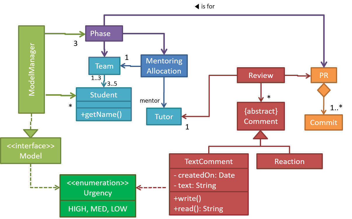
UML class diagrams describe the structure (but not the behavior) of an OOP solution. These are possibly the most often used diagrams in the industry and are an indispensable tool for an OO programmer.
An example class diagram:
Can draw UML classes
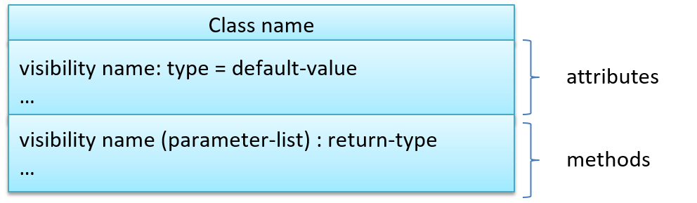
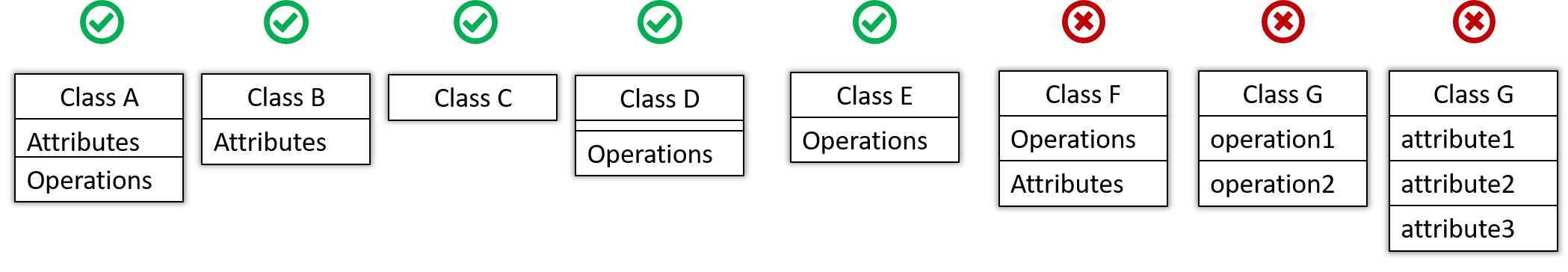
The basic UML notations used to represent a class:
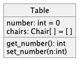
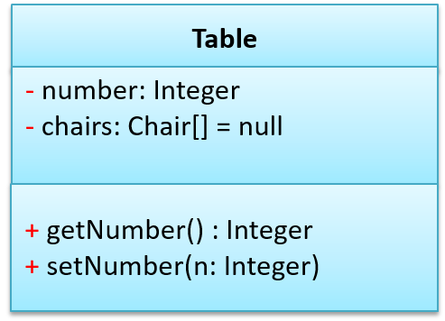
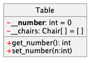
A Table class shown in UML notation:
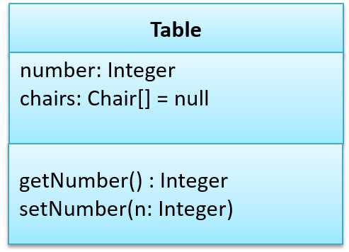
The 'Operations' compartment and/or the 'Attributes' compartment may be omitted if such details are not important for the task at hand. Similarly, some attributes/operations can be omitted if not relevant to the purpose of the diagram. 'Attributes' always appear above the 'Operations' compartment. All operations should be in one compartment rather than each operation in a separate compartment. Same goes for attributes.
The visibility of attributes and operations is used to indicate the level of access allowed for each attribute or operation. The types of visibility and their exact meanings depend on the programming language used. Here are some common visibilities and how they are indicated in a class diagram:
+: public-: private#: protected~: package private
Table class with visibilities shown:
There is no default visibility in UML. If a class diagram does not show the visibility of a , it simply means the visibility is unspecified (for reasons such as the visibility not being decided yet or it being not important to the purpose of the diagram).
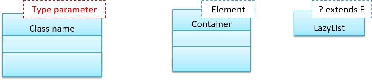
Generic classes can be shown as given below. The notation format is shown on the left, followed by two examples.
Can interpret class-level members in class diagrams
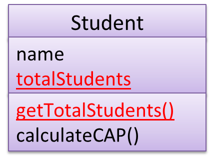
In UML class diagrams, underlines denote class-level attributes and methods.
In the class diagram below, the totalStudents attribute and the getTotalStudents method are class-level.
Can explain/use association labels in class diagrams
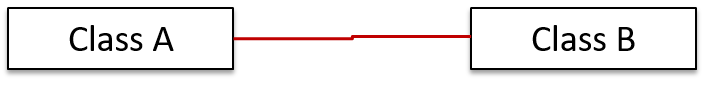
Association labels describe the meaning of the association. The arrow head indicates the direction in which the label is to be read.
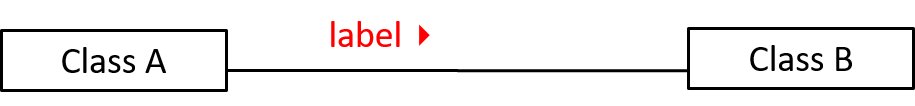
In this example, the same association is described using two different labels.
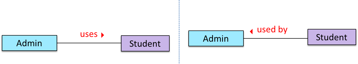
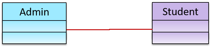
- Diagram on the left:
Adminclass is associated withStudentclass because anAdminobject uses aStudentobject. - Diagram on the right:
Adminclass is associated withStudentclass because aStudentobject is used by anAdminobject.
Can explain/use association roles in class diagrams
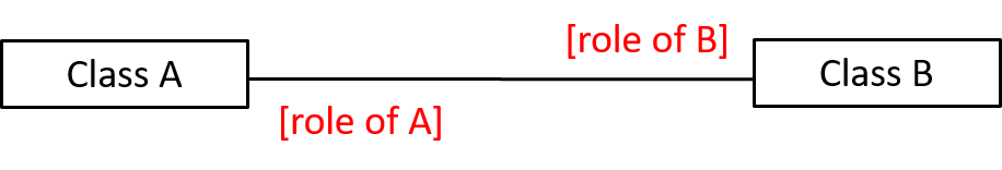
Association Role are used to indicate the role played by the classes in the association.
This association represents a marriage between a Man object and a Woman object. The respective roles played by objects of these two classes are husband and wife.
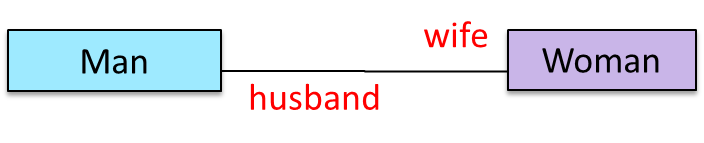
Note how the variable names match closely with the association roles.
class Man {
    Woman wife;
}

class Woman {
    Man husband;
}
class Man:
  def __init__(self):
    self.wife = None # a Woman object

class Woman:
   def __init__(self):
     self.husband = None # a Man object
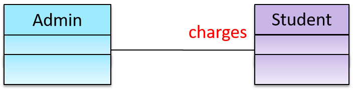
The role of Student objects in this association is charges (i.e. Admin is in charge of students)
class Admin {
    List<Student> charges;
}
class Admin:
  def __init__(self):
    self.charges = [] # list of Student objects
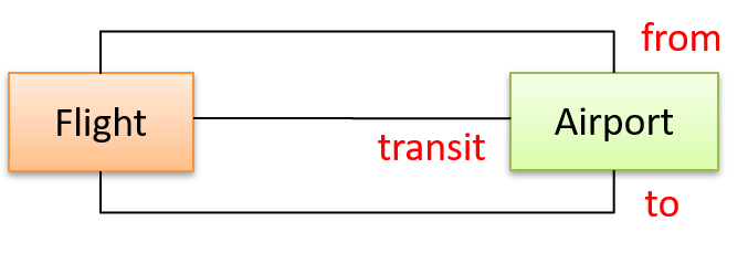
Association roles are optional to show. They are particularly useful for differentiating among multiple associations between the same two classes.
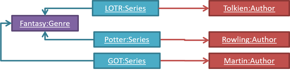
In each the three associations between the Flight class and the Airport class given below, the Airport class plays a different role.
Can explain what is the multiplicity of an association
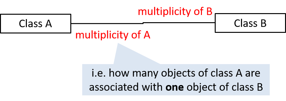
Commonly used multiplicities:
0..1: optional, can be linked to 0 or 1 objects.1: compulsory, must be linked to one object at all times.*: can be linked to 0 or more objects.n..m: the number of linked objects must be withinntominclusive e.g.,2..5,1..*(one or more),*..5(up to five)
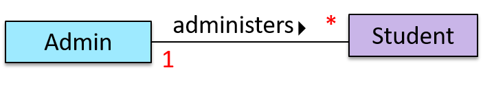
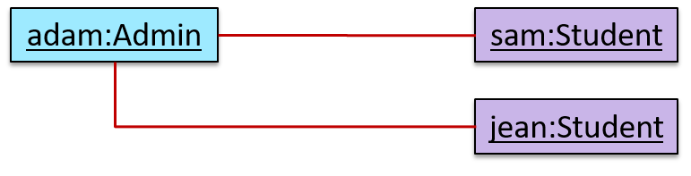
In the diagram below, an Admin object administers (is in charge of) any number of students but a Student object must always be under the charge of exactly one Admin object.
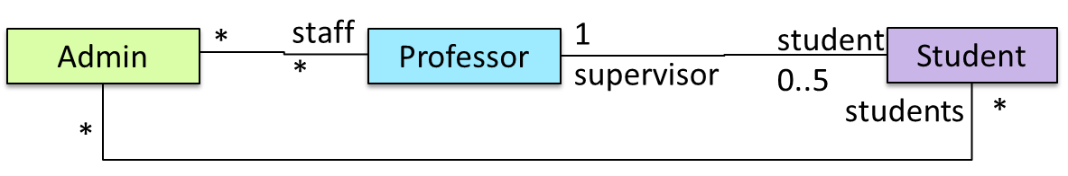
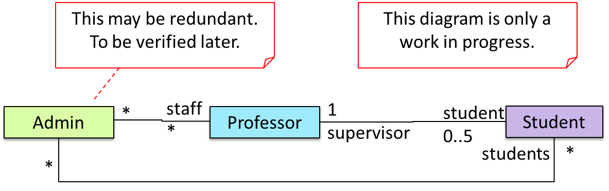
In the diagram below,
- Each student must be supervised by exactly one professor. i.e. There cannot be a student who doesn't have a supervisor or has multiple supervisors.
- A professor cannot supervise more than 5 students but can have no students to supervise.
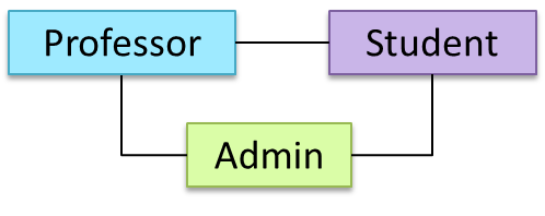
- An admin can handle any number of professors and any number of students, including none.
- A professor/student can be handled by any number of admins, including none.
There is no default multiplicity in UML. If a class diagram does not show the multiplicity of an association, it simply means the multiplicity is unspecified.
Can interpret association navigabilities in class diagrams
Use arrowheads to indicate the navigability of an association.
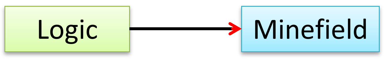
In this example, the navigability is unidirectional, and is from the Logic class to the Minefield class. That means if a Logic object L is associated with a Minefield object M, L has a reference to M but M doesn't have a reference to L.
class Logic {
    Minefield minefield;
    // ...
}

class Minefield {
    //...
}
class Logic:

  def __init__(self):
    self.minefield = None

  # ...


class Minefield:
  # ...
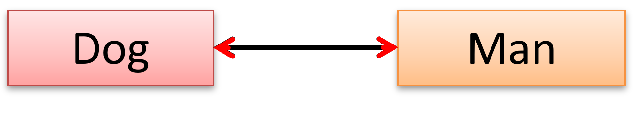
Here is an example of a bidirectional navigability; i.e., if a Dog object d is associated with a Man object m, d has a reference to m and m has a reference to d.
class Dog {
    Man man;
    // ...
}

class Man {
    Dog dog;
    // ...
}
class Dog:

  def __init__(self):
    self.man = None

  # ...


class Man:
  def __init__(self):
    self.dog = None

  # ...
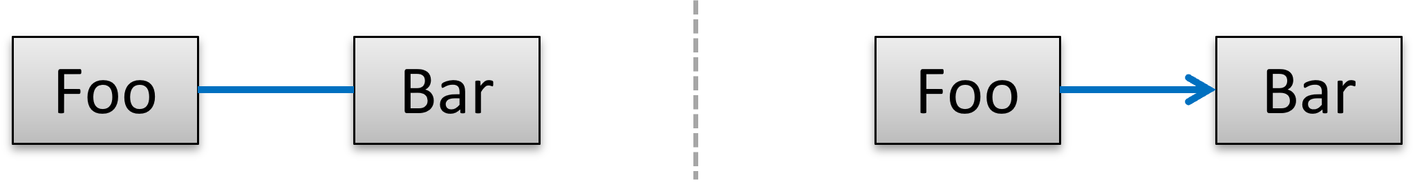
The arrowhead (not the entire arrow) denotes the navigability. The line denotes the association, as before. So, the navigability (i.e., the arrowhead) is an extra annotation added to an association line.
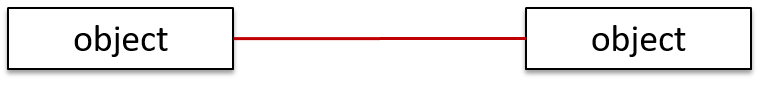
For example, both diagrams below show an association between Foo and Bar. But the one on the right shows the navigability as well.
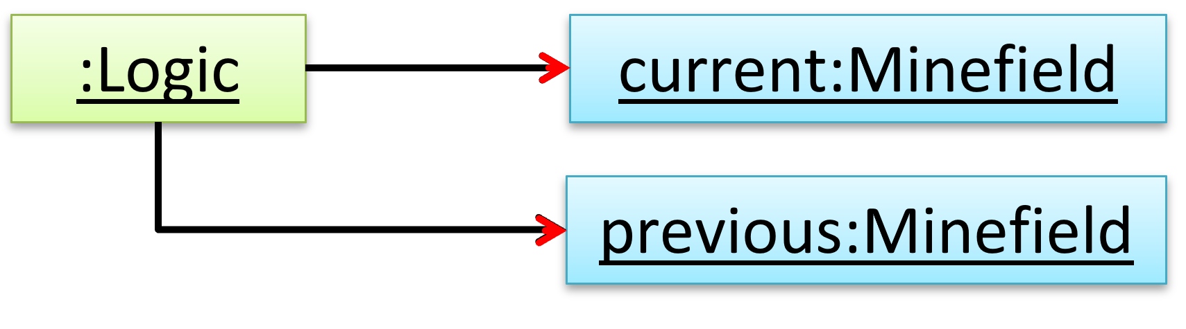
Navigability can be shown in class diagrams as well as object diagrams.
According to this object diagram, the given Logic object is associated with and aware of two MineField objects.
Can show an association as an attribute
An association can be shown as an attribute instead of a line.
Association multiplicities and the default value can be shown as part of the attribute using the following notation. Both are optional.
name: type [multiplicity] = default value
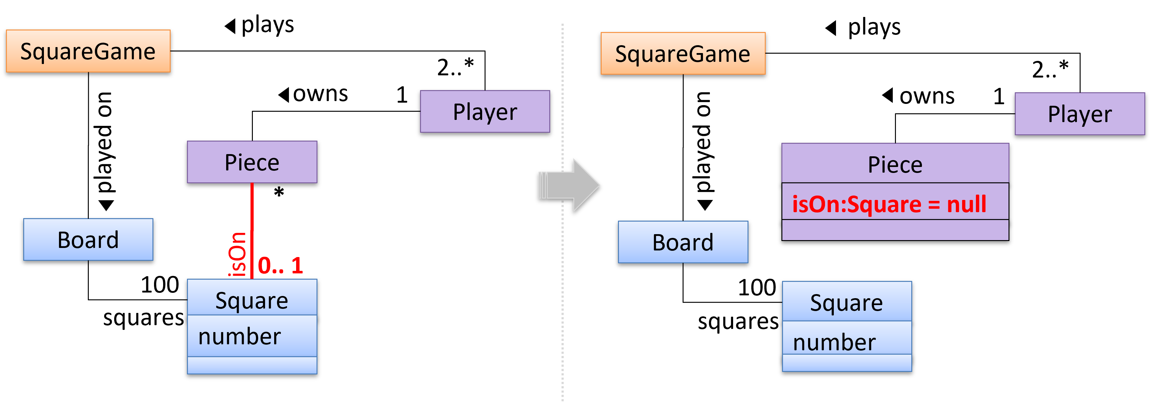
The diagram below depicts a multi-player Square Game being played on a board comprising of 100 squares. Each of the squares may be occupied with any number of pieces, each belonging to a certain player.
A Piece may or may not be on a Square. Note how that association can be replaced by an isOn attribute of the Piece class. The isOn attribute can either be null or hold a reference to a Square object, matching the 0..1 multiplicity of the association it replaces. The default value is null.
The association that a Board has 100 Squares can be shown in either of these two ways:
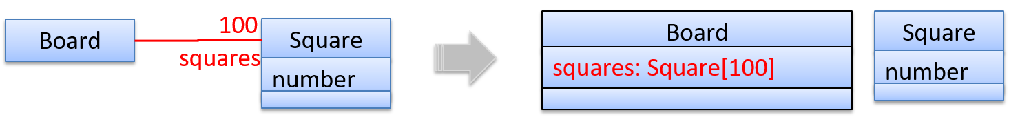
Show each association as either an attribute or a line but not both. A line is preferred as it is easier to spot.
Diagram (a) given below shows the 'author' association between the Book class and the Person class as a line while (b) shows the same association as an attribute in the Book class. Both are correct and the two are equivalent. But (c) is not correct as it uses both a line and an attribute to show the same association.
(a) 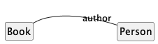
(b) 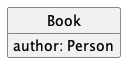
(c) 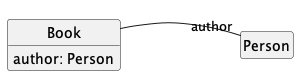
Can draw UML objects
Notation:
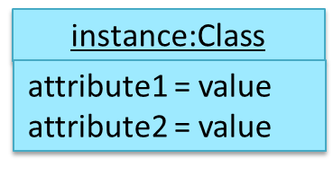
Notes:
- The class name and object name are underlined e.g.
car1:Car. objectName:ClassNameis meant to say 'an instance ofClassNameidentified asobjectName'.- Unlike classes, there is no compartment for methods.
- Attributes compartment can be omitted if it is not relevant to the purpose of the diagram.
- Object name can be omitted too e.g.
:Carwhich is meant to say 'an unnamed instance of aCarobject'.
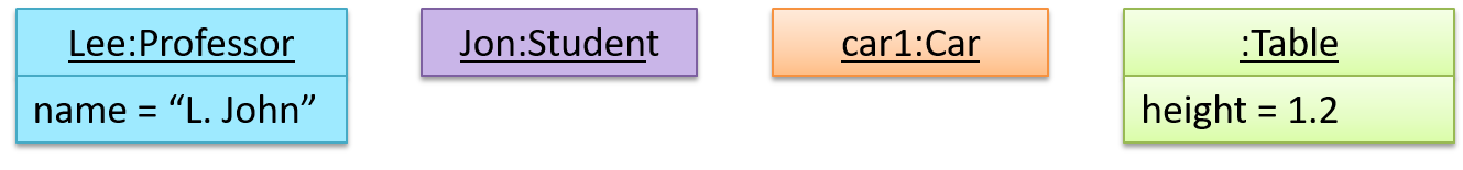
Some example objects:
Can distinguish between class diagrams and object diagrams
Compared to the notation for class diagrams, object diagrams differ in the following ways:
- Show objects instead of classes:
- Instance name may be shown
- There is a
:before the class name - Instance and class names are underlined
- Methods are omitted
- Multiplicities are omitted. Reason: an association line in an object diagram represents a connection to exactly one object (i.e., the multiplicity is always 1).
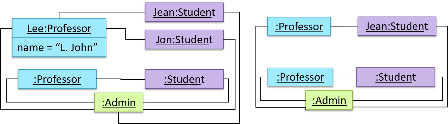
Furthermore, multiple object diagrams can correspond to a single class diagram.
Both object diagrams are derived from the same class diagram shown earlier. In other words, each of these object diagrams shows ‘an instance of’ the same class diagram.
When the class diagram has an inheritance relationship, the object diagram should show either an object of the parent class or the child class, but not both.
Suppose Employee is a child class of the Person class. The class diagram will be as follows:

Now, how do you show an Employee object named jake?
 This is not correct, as there should be only one object.
 This is OK.
 This is OK, as
 jakeis aPersontoo. That is, we can show the parent class instead of the child class if the child class doesn't matter to the purpose of the diagram (i.e., the reader of this diagram will not need to know thatjakeis in fact anEmployee).
Association labels/roles can be omitted unless they add value (e.g., showing them is useful if there are multiple associations between the two classes in concern -- otherwise you wouldn't know which association the object diagram is showing)
Consider this class diagram and the object diagram:
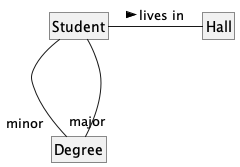
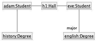
We can clearly see that both Adam and Eve lives in hall h1 (i.e., OK to omit the association label lives in) but we can't see if History is Adam's major or his minor (i.e., the diagram should have included either an association label or a role there). In contrast, we can see Eve is an English major.
Follow up notes for the item(s) above:
After learning the UML notations above, do the following in the given order:
- Attempt this week's Canvas quiz. It will help you solidify your knowledge of the UML notation covered so far.
- Watch the video given below.. It contains a step-by-step example of drawing UML diagrams.