This site is from a past semester! The current version will be here when the new semester starts.

Week 4 [Mon, Jan 30th] - SE Topics

Detailed Table of Contents


[W4.1] OOP: Objects

W4.1a

Paradigms → OOP → Introduction → What

Video

Can describe OOP at a higher level

Object-Oriented Programming (OOP) is a programming paradigm. A programming paradigm guides programmers to analyze programming problems, and structure programming solutions, in a specific way.

Programming languages have traditionally divided the world into two parts—data and operations on data. Data is static and immutable, except as the operations may change it. The procedures and functions that operate on data have no lasting state of their own; they’re useful only in their ability to affect data.

This division is, of course, grounded in the way computers work, so it’s not one that you can easily ignore or push aside. Like the equally pervasive distinctions between matter and energy and between nouns and verbs, it forms the background against which you work. At some point, all programmers—even object-oriented programmers—must lay out the data structures that their programs will use and define the functions that will act on the data.

With a procedural programming language like C, that’s about all there is to it. The language may offer various kinds of support for organizing data and functions, but it won’t divide the world any differently. Functions and data structures are the basic elements of design.

Object-oriented programming doesn’t so much dispute this view of the world as restructure it at a higher level. It groups operations and data into modular units called objects and lets you combine objects into structured networks to form a complete program. In an object-oriented programming language, objects and object interactions are the basic elements of design.

-- Object-Oriented Programming with Objective-C, Apple

Some other examples of programming paradigms are:

Paradigm Programming Languages
Procedural Programming paradigm C
Functional Programming paradigm F#, Haskell, Scala
Logic Programming paradigm Prolog

Some programming languages support multiple paradigms.

Java is primarily an OOP language but it supports limited forms of functional programming and it can be used to (although not recommended) write procedural code. e.g. se-edu/addressbook-level1

JavaScript and Python support functional, procedural, and OOP programming.

Exercises


W4.1b

Paradigms → OOP → Objects → What

Video

Can describe how OOP relates to the real world

Every object has both state (data) and behavior (operations on data). In that, they’re not much different from ordinary physical objects. It’s easy to see how a mechanical device, such as a pocket watch or a piano, embodies both state and behavior. But almost anything that’s designed to do a job does, too. Even simple things with no moving parts such as an ordinary bottle combine state (how full the bottle is, whether or not it’s open, how warm its contents are) with behavior (the ability to dispense its contents at various flow rates, to be opened or closed, to withstand high or low temperatures).

It’s this resemblance to real things that gives objects much of their power and appeal. They can not only model components of real systems, but equally as well fulfill assigned roles as components in software systems.

-- Object-Oriented Programming with Objective-C, Apple

Object Oriented Programming (OOP) views the world as a network of interacting objects.

A real world scenario viewed as a network of interacting objects:

You are asked to find out the average age of a group of people Adam, Beth, Charlie, and Daisy. You take a piece of paper and pen, go to each person, ask for their age, and note it down. After collecting the age of all four, you enter it into a calculator to find the total. And then, use the same calculator to divide the total by four, to get the average age. This can be viewed as the objects You, Pen, Paper, Calculator, Adam, Beth, Charlie, and Daisy interacting to accomplish the end result of calculating the average age of the four persons. These objects can be considered as connected in a certain network of certain structure.

OOP solutions try to create a similar object network inside the computer’s memory – a sort of virtual simulation of the corresponding real world scenario – so that a similar result can be achieved programmatically.

OOP does not demand that the virtual world object network follow the real world exactly.

Our previous example can be tweaked a bit as follows:

  • Use an object called Main to represent your role in the scenario.
  • As there is no physical writing involved, you can replace the Pen and Paper with an object called AgeList that is able to keep a list of ages.

Every object has both state (data) and behavior (operations on data).

Object Real World? Virtual World? Example of State (i.e. Data) Examples of Behavior (i.e. Operations)
Adam Name, Date of Birth Calculate age based on birthday
Pen - Ink color, Amount of ink remaining Write
AgeList - Recorded ages Give the number of entries, Accept an entry to record
Calculator Numbers already entered Calculate the sum, divide
You/Main Average age, Sum of ages Use other objects to calculate

Every object has an interface and an implementation.

Every real world object has:

  • an interface through which other objects can interact with it
  • an implementation that supports the interface but may not be accessible to the other object

The interface and implementation of some real-world objects in our example:

  • Calculator: the buttons and the display are part of the interface; circuits are part of the implementation.
  • Adam: In the context of our 'calculate average age' example, the interface of Adam consists of requests that Adam will respond to, e.g. "Give age to the nearest year, as at Jan 1st of this year" "State your name"; the implementation includes the mental calculation Adam uses to calculate the age which is not visible to other objects.

Similarly, every object in the virtual world has an interface and an implementation.

The interface and implementation of some virtual-world objects in our example:

  • Adam: the interface might have a method getAge(Date asAt); the implementation of that method is not visible to other objects.

Objects interact by sending messages. Both real world and virtual world object interactions can be viewed as objects sending messages to each other. The message can result in the sender object receiving a response and/or the receiver object’s state being changed. Furthermore, the result can vary based on which object received the message, even if the message is identical (see rows 1 and 2 in the example below).

Examples:

World Sender Receiver Message Response State Change
Real You Adam "What is your name?" "Adam" -
Real as above Beth as above "Beth" -
Real You Pen Put nib on paper and apply pressure Makes a mark on your paper Ink level goes down
Virtual Main Calculator (current total is 50) add(int i): int i = 23 73 total = total + 23

Exercises


W4.1c

Paradigms → OOP → Objects → Objects as abstractions

Video

Can explain the abstraction aspect of OOP

The concept of Objects in OOP is an abstraction mechanism because it allows us to abstract away the lower level details and work with bigger granularity entities i.e. ignore details of data formats and the method implementation details and work at the level of objects.

You can deal with a Person object that represents the person Adam and query the object for Adam's age instead of dealing with details such as Adam’s date of birth (DoB), in what format the DoB is stored, the algorithm used to calculate the age from the DoB, etc.


W4.1d

Paradigms → OOP → Objects → Encapsulation of objects

Video

Can explain the encapsulation aspect of OOP

Encapsulation protects an implementation from unintended actions and from inadvertent access.
-- Object-Oriented Programming with Objective-C, Apple

An object is an encapsulation of some data and related behavior in terms of two aspects:

1. The packaging aspect: An object packages data and related behavior together into one self-contained unit.

2. The information hiding aspect: The data in an object is hidden from the outside world and are only accessible using the object's interface.

Exercises


[W4.2] Requirements: Use Cases

Video

W4.2a

Requirements → Specifying Requirements → Use Cases → Introduction

Can explain use cases

Use case: A description of a set of sequences of actions, including variants, that a system performs to yield an observable result of value to an actor [ 📖 : ].

A use case describes an interaction between the user and the system for a specific functionality of the system.

Example 1: 'transfer money' use case for an online banking system

System: Online Banking System (OBS)
Use case: UC23 - Transfer Money
Actor: User
MSS:
  1. User chooses to transfer money.
  2. OBS requests for details of the transfer.
  3. User enters the requested details.
  4. OBS requests for confirmation.
  5. User confirms.
  6. OBS transfers the money and displays the new account balance.
  Use case ends.
Extensions:
  3a. OBS detects an error in the entered data.
      3a1. OBS requests for the correct data.
      3a2. User enters new data.
      Steps 3a1-3a2 are repeated until the data entered are correct.
      Use case resumes from step 4.

  3b. User requests to effect the transfer in a future date.
      3b1. OBS requests for confirmation.
      3b2. User confirms future transfer.
      Use case ends.

  *a. At any time, User chooses to cancel the transfer.
      *a1. OBS requests to confirm the cancellation.
      *a2. User confirms the cancellation.
      Use case ends.

Example 2: 'upload file' use case of an LMS


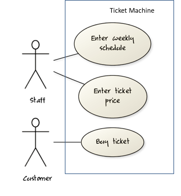
UML includes a diagram type called use case diagrams that can illustrate use cases of a system visually, providing a visual ‘table of contents’ of the use cases of a system.

In the example on the right, note how use cases are shown as ovals and user roles relevant to each use case are shown as stick figures connected to the corresponding ovals.

Use cases capture the functional requirements of a system.


W4.2b

Requirements → Specifying Requirements → Use Cases → Identifying

Can use use cases to list functional requirements of a simple system

A use case is an interaction between a system and its actors.

Actors in Use Cases

Actor: An actor (in a use case) is a role played by a user. An actor can be a human or another system. Actors are not part of the system; they reside outside the system.

Some example actors for a Learning Management System:

  • Actors: Guest, Student, Staff, Admin, , .

A use case can involve multiple actors.

  • Software System: LearnSys
  • Use case: UC01 Conduct Survey
  • Actors: Staff, Student

An actor can be involved in many use cases.

  • Software System: LearnSys
  • Actor: Staff
  • Use cases: UC01 Conduct Survey, UC02 Set Up Course Schedule, UC03 Email Class, ...

A single person/system can play many roles.

  • Software System: LearnSys
  • Person: a student
  • Actors (or Roles): Student, Guest, Tutor

Many persons/systems can play a single role.

  • Software System: LearnSys
  • Actor (or role): Student
  • Persons that can play this role: undergraduate student, graduate student, a staff member doing a part-time course, exchange student

Use cases can be specified at various levels of detail.

Consider the three use cases given below. Clearly, (a) is at a higher level than (b) and (b) is at a higher level than (c).

  • System: LearnSys
  • Use cases:
    a. Conduct a survey
    b. Take the survey
    c. Answer survey question

While modeling user-system interactions,

  • Start with high level use cases and progressively work toward lower level use cases.
  • Be mindful of which level of detail you are working at and not to mix use cases of different levels.

Exercises


W4.2c

Requirements → Specifying Requirements → Use Cases → Details

Requirements → Specifying Requirements → Use Cases → Introduction


Can specify details of a use case in a structured format

Writing use case steps

The main body of the use case is a sequence of steps that describes the interaction between the system and the actors. Each step is given as a simple statement describing who does what.

An example of the main body of a use case.

  1. Student requests to upload file
  2. LMS requests for the file location
  3. Student specifies the file location
  4. LMS uploads the file

A use case describes only the externally visible behavior, not internal details, of a system i.e. should minimize details that are not part of the interaction between the user and the system.

This example use case step refers to behaviors not externally visible.

  1. LMS saves the file into the cache and indicates success.

A step gives the intention of the actor (not the mechanics). That means UI details are usually omitted. The idea is to leave as much flexibility to the UI designer as possible. That is, the use case specification should be as general as possible (less specific) about the UI.

The first example below is not a good use case step because it contains UI-specific details. The second one is better because it omits UI-specific details.

Bad : User right-clicks the text box and chooses ‘clear’

Good : User clears the input

A use case description can show loops too.

An example of how you can show a loop:

Software System: SquareGame
Use case: - Play a Game
Actors: Player (multiple players)
MSS:

  1. A Player starts the game.
  2. SquareGame asks for player names.
  3. Each Player enters his own name.
  4. SquareGame shows the order of play.
  5. SquareGame prompts for the current Player to throw a die.
  6. Current Player adjusts the throw speed.
  7. Current Player triggers the die throw.
  8. SquareGame shows the face value of the die.
  9. SquareGame moves the Player's piece accordingly.
    Steps 5-9 are repeated for each Player, and for as many rounds as required until a Player reaches the 100th square.
  10. SquareGame shows the Winner.

Use case ends.

The Main Success Scenario (MSS) describes the most straightforward interaction for a given use case, which assumes that nothing goes wrong. This is also called the Basic Course of Action or the Main Flow of Events of a use case.

Note how the MSS in the example below assumes that all entered details are correct and ignores problems such as timeouts, network outages etc. For example, the MSS does not tell us what happens if the user enters incorrect data.

System: Online Banking System (OBS)
Use case: UC23 - Transfer Money
Actor: User
MSS:

  1. User chooses to transfer money.
  2. OBS requests for details of the transfer.
  3. User enters the requested details.
  4. OBS requests for confirmation.
  5. OBS transfers the money and displays the new account balance.

Use case ends.

Extensions are "add-on"s to the MSS that describe exceptional/alternative flow of events. They describe variations of the scenario that can happen if certain things are not as expected by the MSS. Extensions appear below the MSS.

This example adds some extensions to the use case in the previous example.

System: Online Banking System (OBS)
Use case: UC23 - Transfer Money
Actor: User
MSS:
  1. User chooses to transfer money.
  2. OBS requests for details of the transfer.
  3. User enters the requested details.
  4. OBS requests for confirmation.
  5. User confirms.
  6. OBS transfers the money and displays the new account balance.
  Use case ends.
Extensions:
  3a. OBS detects an error in the entered data.
      3a1. OBS requests for the correct data.
      3a2. User enters new data.
      Steps 3a1-3a2 are repeated until the data entered are correct.
      Use case resumes from step 4.
  
  3b. User requests to effect the transfer in a future date.
      3b1. OBS requests for confirmation.
      3b2. User confirms future transfer.
      Use case ends.
  
  *a. At any time, User chooses to cancel the transfer.
      *a1. OBS requests to confirm the cancellation.
      *a2. User confirms the cancellation.
      Use case ends.

  *b. At any time, 120 seconds lapse without any input from the User.
      *b1. OBS cancels the transfer.
      *b2. OBS informs the User of the cancellation.
      Use case ends.

Note that the numbering style is not a universal rule but a widely used convention. Based on that convention,

  • either of the extensions marked 3a. and 3b. can happen just after step 3 of the MSS.
  • the extension marked as *a. can happen at any step (hence, the *).

When separating extensions from the MSS, keep in mind that the MSS should be self-contained. That is, the MSS should give us a complete usage scenario.

Also note that it is not useful to mention events such as power failures or system crashes as extensions because the system cannot function beyond such catastrophic failures.

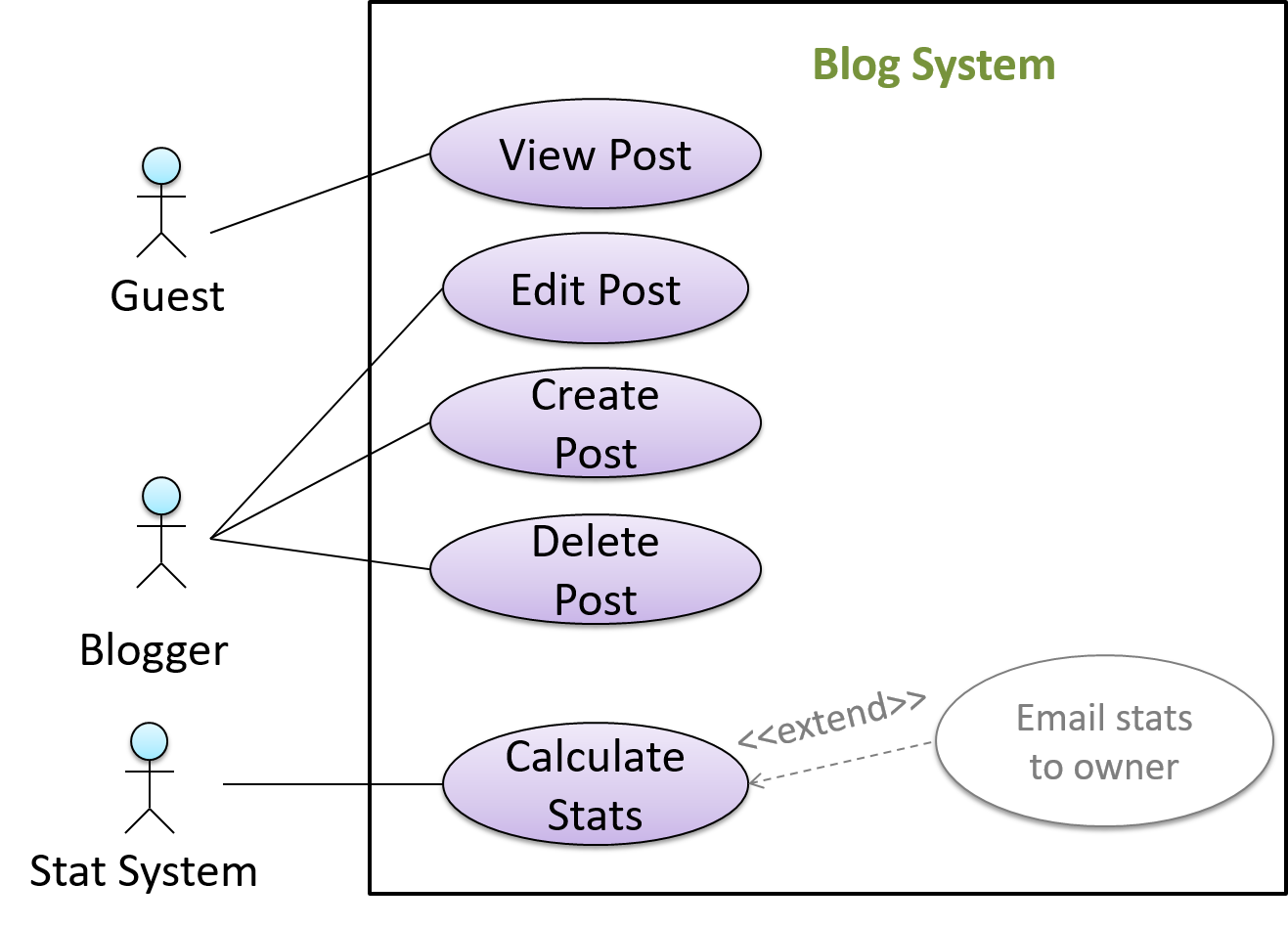
In use case diagrams you can use the <<extend>> arrows to show extensions. Note the direction of the arrow is from the extension to the use case it extends and the arrow uses a dashed line.

A use case can include another use case. Underlined text is used to show an inclusion of a use case.

This use case includes two other use cases, one in step 1 and one in step 2.

  • Software System: LearnSys
  • Use case: UC01 - Conduct Survey
  • Actors: Staff, Student
  • MSS:
    1. Staff creates the survey (UC44).
    2. Student completes the survey (UC50).
    3. Staff views the survey results.
      Use case ends.

Inclusions are useful,

  • when you don't want to clutter a use case with too many low-level steps.
  • when a set of steps is repeated in multiple use cases.

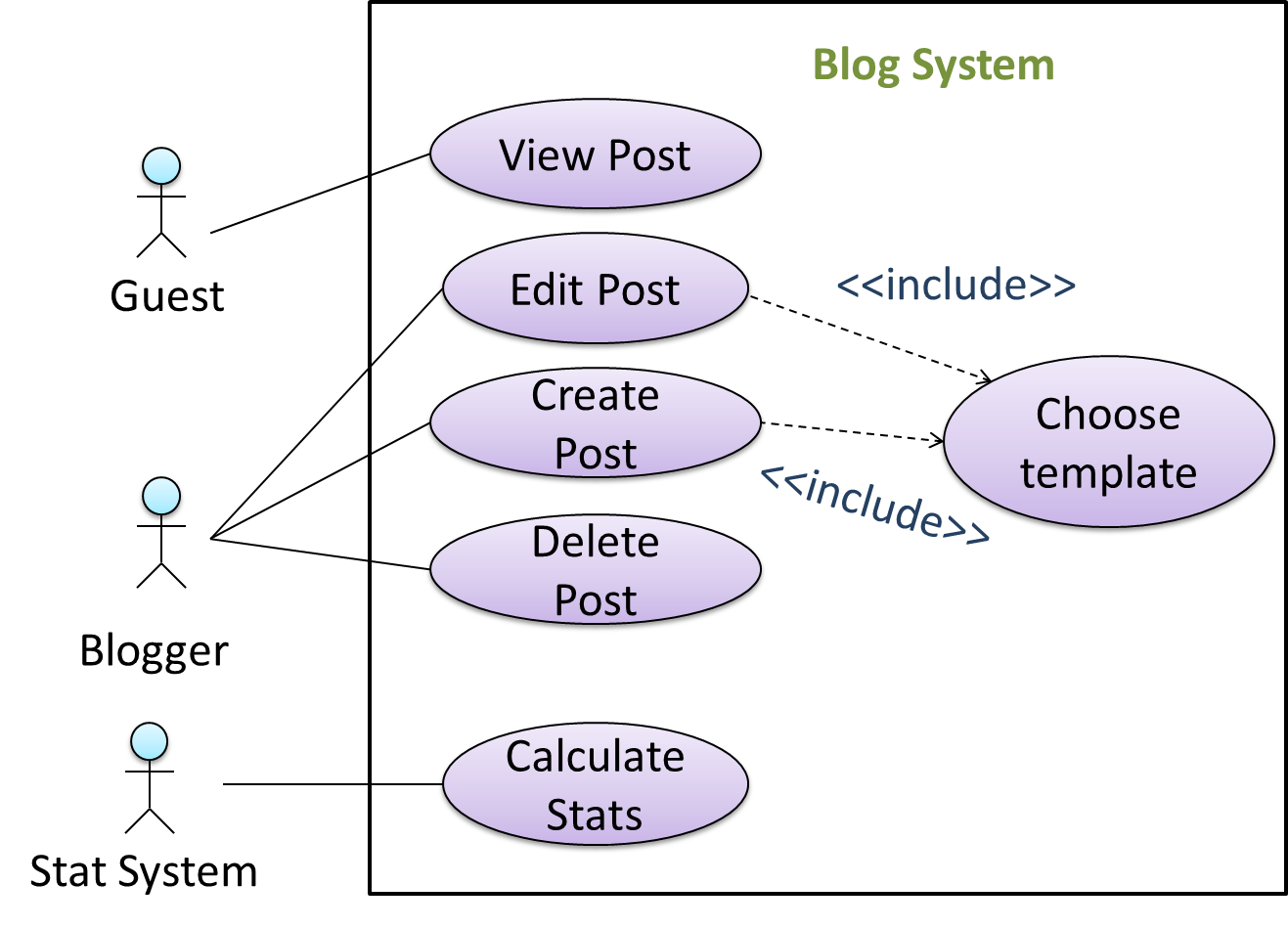
You use a dotted arrow and an <<include>> annotation to show use case inclusions in a use case diagram. Note how the arrow direction is different from the <<extend>> arrows.

Preconditions specify the specific state you expect the system to be in before the use case starts.

Software System: Online Banking System
Use case: UC23 - Transfer Money
Actor: User
Preconditions: User is logged in
MSS:

  1. User chooses to transfer money.
  2. OBS requests for details for the transfer.
    ...

Guarantees specify what the use case promises to give us at the end of its operation.

Software System: Online Banking System
Use case: UC23 - Transfer Money
Actor: User
Preconditions: User is logged in.
Guarantees:

  • Money will be deducted from the source account only if the transfer to the destination account is successful.
  • The transfer will not result in the account balance going below the minimum balance required.

MSS:

  1. User chooses to transfer money.
  2. OBS requests for details for the transfer.
    ...

Exercises


W4.2d

Requirements → Specifying Requirements → Use Cases → Usage

Can optimize the use of use cases

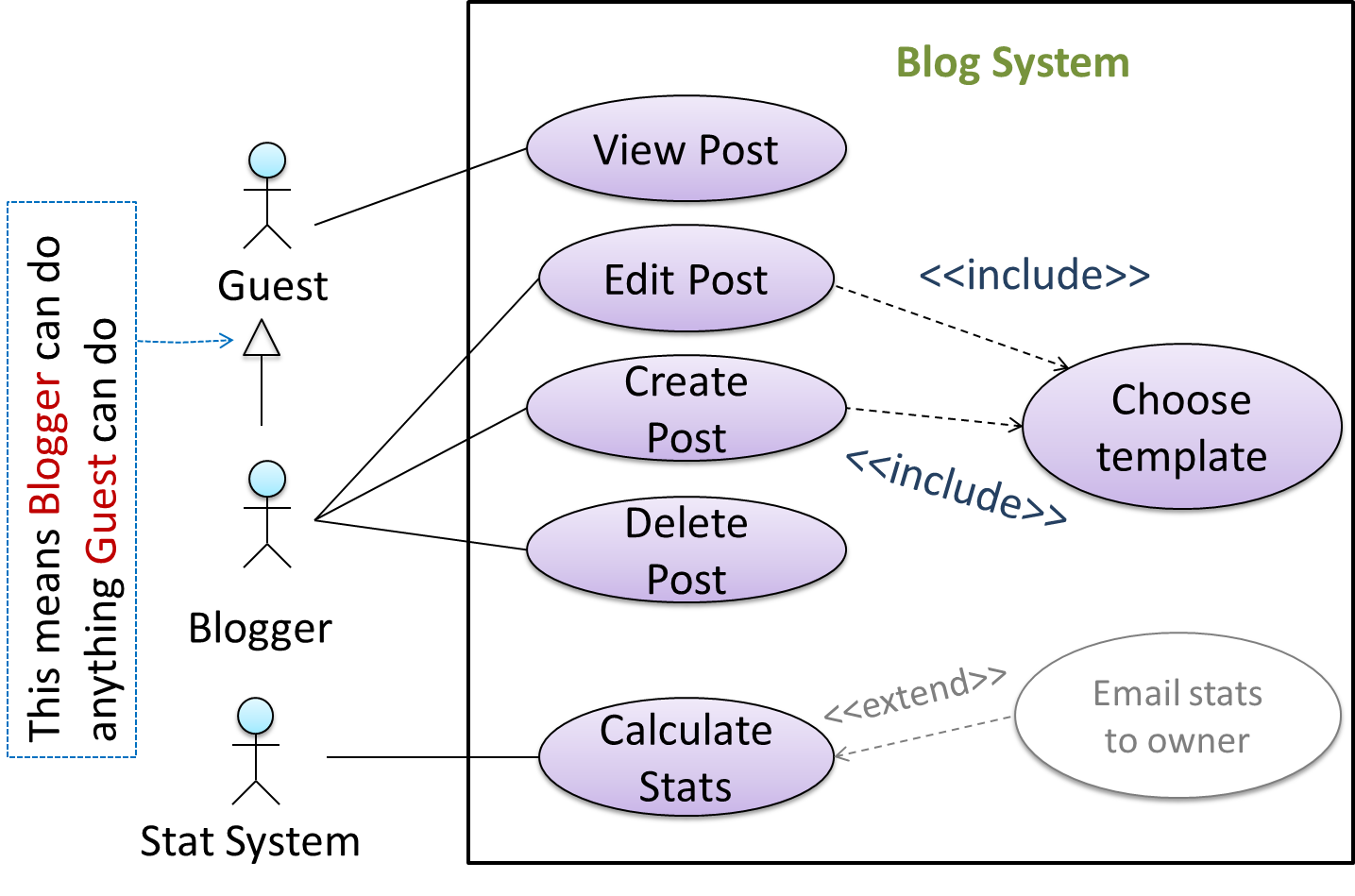
You can use actor generalization in use case diagrams using a symbol similar to that of UML notation for inheritance.

In this example, actor Blogger can do all the use cases the actor Guest can do, as a result of the actor generalization relationship given in the diagram.

Do not over-complicate use case diagrams by trying to include everything possible. A use case diagram is a brief summary of the use cases that is used as a starting point. Details of the use cases can be given in the use case descriptions.

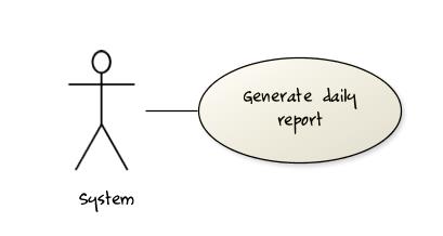
Some include ‘System’ as an actor to indicate that something is done by the system itself without being initiated by a user or an external system.

The diagram below can be used to indicate that the system generates daily reports at midnight.

However, others argue that only use cases providing value to an external user/system should be shown in the use case diagram. For example, they argue that view daily report should be the use case and generate daily report is not to be shown in the use case diagram because it is simply something the system has to do to support the view daily report use case.

You are recommended to follow the latter view (i.e. not to use System as a user). Limit use cases for modeling behaviors that involve an external actor.

UML is not very specific about the text contents of a use case. Hence, there are many styles for writing use cases. For example, the steps can be written as a continuous paragraph.

Use cases should be easy to read. Note that there is no strict rule about writing all details of all steps or a need to use all the elements of a use case.

There are some advantages of documenting system requirements as use cases:

  • Because they use a simple notation and plain English descriptions, they are easy for users to understand and give feedback.
  • They decouple user intention from mechanism (note that use cases should not include UI-specific details), allowing the system designers more freedom to optimize how a functionality is provided to a user.
  • Identifying all possible extensions encourages us to consider all situations that a software product might face during its operation.
  • Separating typical scenarios from special cases encourages us to optimize the typical scenarios.

One of the main disadvantages of use cases is that they are not good for capturing requirements that do not involve a user interacting with the system. Hence, they should not be used as the sole means to specify requirements.

Exercises


Follow up notes for the item(s) above:

Now that you know all the different ways of specifying requirements, here is an example that shows how all techniques of specifying requirements can work together:

Video Example: TeamFormer